Product & Service
NCTE Torque sensor S3000
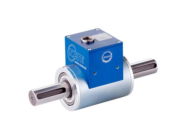
Main areas of application for the 3000 Series
- Labs
- Test facilities
- Quality assurance
Distinctive features
- Made in Germany
- Short delivery time
- Excellent price/performance ratio
- Integrated electronic (Plug & Play)
- Completely contactless measuring system
- Delivery including 5 m cable and calibration certificate
- Suitable accessories (readout unit, couplings)
Technical data
- Nominal torque: up to 2000 Nm, bidirectional
- Speed: ≤ 10000 rpm
- Accuracy: ≤ ±0.2 %
- Operating temperature: -40°C to +85°C
- Protection class: IP50
- Output signal options: 0-10V / 4-20 mA
- Cut-off frequency: 2500 Hz
Torque ranges
|
Model line Series 3000 Round shaft |
Nominal torque bidirectional (+/-) [Nm] |
Limiting torque unidirectional [Nm] |
Limiting torque bidirectional (+/-) [Nm] |
RPM [rpm] |
|
Ø 15 mm |
50 |
65 |
65 |
10000 |
|
100 |
130 |
130 |
||
|
Ø 25 mm |
250 |
325 |
325 |
8000 |
|
500 |
650 |
650 |
||
|
Ø 40 mm |
1000 |
1300 |
1300 |
5000 |
|
2000 |
2600 |
2600 |
|
Model line Series 3000 Square shaft |
Nominal torque bidirectional (+/-) [Nm] |
Limiting torque unidirectional [Nm] |
Limiting torque bidirectional (+/-) [Nm] |
RPM [rpm] |
|
⅜ inch |
50 |
50 |
35 |
10000 |
|
¾ inch |
250 |
250 |
250 |
8000 |
|
1 inch |
1000 |
1000 |
670 |
5000 |
Note: In case of overload, the sensor leads to a measurement offset. In such case, the sensor needs to be recalibrated at NCTE AG. The sensor should be operated only within the specified nominal torque range.
Load characteristics
|
Model line Series 3000 Measuring range |
Axial force [N]1 |
Limit transverse force [N] |
Limit bending moment [Nm] |
|
50 and 100 |
2300 |
300 |
41.7 |
|
250 and 500 |
7000 |
800 |
176 |
|
1000 and 2000 |
24000 |
200 |
700 |
Any irregular stress (bending moment, transverse or axial force, exceeding the nominal torque) up to the specified static load limit is only permissible as long as none of the other stresses can occur. Otherwise the limit values must be reduced. If 30 % of the limit bending moment and 30 % of the limit transverse force are present in each case, only 40 % of the axial force is permissible, whereby the nominal torque must not be exceeded.
If you are interesting this products, please download the catalog now. A sales representative will contact with you as soon as possible
© 2019 Chief SI INC. - Design By Armlet